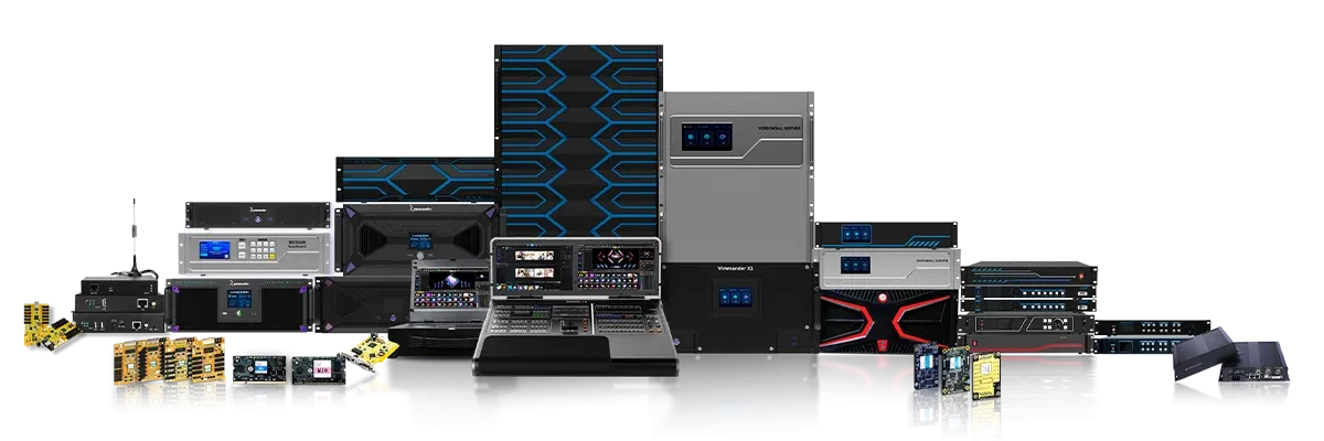
Device names in an LED system are often used as if they describe the same job. They do not. A video processor prepares incoming pictures, a sending card converts the finished raster into LED data, and an integrated controller can combine both roles. Identifying the missing function in the signal chain is the clearest way to choose an LED control device without duplicating hardware.
A Video Processor Shapes Standard Video
The processor sits close to the source side of the chain. It accepts formats such as HDMI, DisplayPort, DVI, or SDI, then may scale, crop, switch, or compose them into the canvas needed by the display.
A processor becomes important when sources have different resolutions, multiple windows must appear together, or a large wall needs splicing and flexible layouts. On its own, this LED control device category may still require a sending stage before the cabinets can interpret the signal.
Processor capacity is described by input bandwidth, accepted interfaces, layer count, canvas dimensions, and output routes. Those figures should be evaluated against simultaneous use. A chassis that accepts many input cards may have different limits for the number of active 4K sources, windows, or outputs.
A Sending Card Translates the Finished Raster
LED receiving cards do not normally consume an ordinary HDMI image directly. A sending card converts video into the distributed data stream used by the receiving cards and assigns pixel regions to Ethernet or fiber outputs.
It is the appropriate LED control device when upstream content already has the correct size and composition but still needs to enter the LED transmission chain. Selection depends on total pixels, maximum width and height, number of output ports, transmission distance, and resilience.
Mapping functions can accommodate cabinet wiring, while port backup can preserve output after certain cable faults. Fiber interfaces serve long-distance layouts, but they remain model-specific and must be paired with the correct receiving or conversion equipment.
Kystar‘s ES series demonstrates the sending-card role. Output count and load scale together across the three models: ES6 pairs 6 Gigabit Ethernet outputs with about 2.35 million pixels, ES10 pairs 10 outputs with about 6.5 million pixels, and ES20 pairs 20 outputs with about 8.85 million pixels.
ES10 and ES20 support HDMI 2.0-class 4K input, while ES20 adds DP1.2 input and four 10G optical interfaces arranged as main and backup outputs. Mapping and Ethernet-port backup are also available on designated models within the range.
An Integrated Controller Combines Preparation and Sending
An integrated video controller receives standard video, processes the image, and sends LED data from the same chassis. This LED control device can shorten the signal chain for projects that need scaling, source management, and LED output but do not require a large modular splicing platform.
The integration also creates one configuration boundary for the processor and sending stages. Kystar KLSxC models cover different scales. KLS2c and KLS4c manage one screen, KLS6c through KLS12c support three independent screens, and KLS16c/KLS24c support up to eight screens plus an OSD layer.
Models with six or more Ethernet ports accept 4K-class input; exact timing and interface capability depend on the model. The series supports custom resolutions, non-rectangular loading, and multi-unit frame synchronization on KLS6c and above, while KLS16c/KLS24c add HDMI 2.0, DisplayPort 1.2, fiber, and model-specific 3D functions.
Larger Layouts May Need Another Class of System
A sending card or compact controller is not a substitute for extensive real-time composition. When a project requires many sources, large numbers of windows, preview, routing, irregular multi-screen canvases, or 8K workflows, a splicing processor may become the necessary LED control device. If content itself must be rendered, synchronized, and played across outputs, a media server may sit even further upstream.
Kystar SEn processors focus on modular video processing and output routing, while SHn systems combine switching, splicing, and LED control. Kommander media servers originate and synchronize demanding visual content. These products can share a project, but their capacities should not be added without a diagram showing which stage performs each job.
Decide by the Function the Chain Lacks
If a correctly sized source only needs conversion and distribution to receiving cards, a sending card is the direct answer. If the source also needs scaling, source switching, or modest multi-screen handling, an integrated controller may be more economical. If multi-source composition and large-canvas routing dominate, a processor belongs in the design.
The chosen hardware should remove a specific gap rather than repeat a function already provided elsewhere. The final device category follows the missing function in the existing chain, not the most comprehensive feature list available. A block diagram is the simplest validation tool.
It labels source timing, every scaling stage, the point where LED data is generated, output links, and receiving-card topology. Capacities can then be checked where they apply, and unnecessary conversions become visible. During commissioning, test patterns verify port mapping, while moving content and controlled cable interruptions examine synchronization and backup behavior.
That evidence confirms the assigned role more reliably than the product name on a chassis. A useful specification records source formats, native LED raster, screen count, window count, port and distance requirements, mapping, synchronization, and backup behavior.
The LED control device can then be matched to verified model data. Kystar offers sending, integrated-control, splicing, and media-server paths, but the project’s signal chain—not the broadest product label—determines which one is required.
